

- New

How to Place an Order

Store Pick Up

Request for Quotation/ International Sourcing

Order Status

Reference: RBD-1354
Length: 8 inches/20 CM (Long) Material: Copper Plated Pin Spacing: 2.54mm.
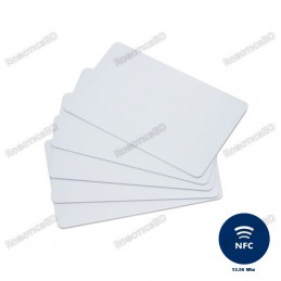
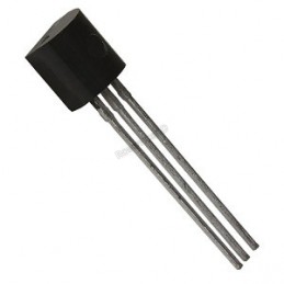
Reference: RBD-0351
Contactless transmission of data and supply energy (no battery needed) Operating distance: Up to 100mm (depending on antenna geometry) RoboticsBD Operating frequency: 13.56MHz Data transfer: 106 kbit/s Data integrity: 16 Bit CRC, parity, bit coding bit counting Anticollision Typical ticketing transaction: <100 ms ( including backup management)...
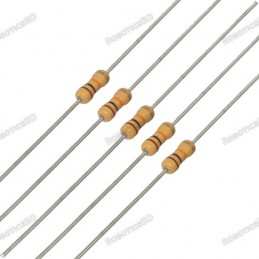
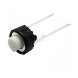
Reference: 0245
Choose your desire Resistor value from below:
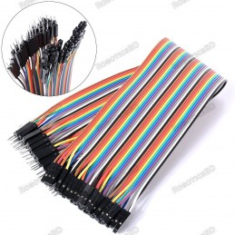
Reference: 0031
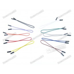
3 Types Available (Please select from option) 1. Male to Male 2. Male to Female 3. Female-Female
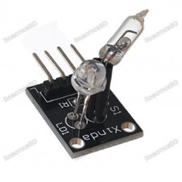
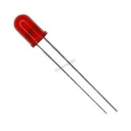
Reference: RBD-0768
Size: 5mm Color: RED Head Shape: Round Lens Appearance: Transparent
Reference: RBD-0761
Breadboard friendly Mounting Style: Through Hole Mounting Direction: Vertical
Reference: 1353
Length: 12.5 inches/30 CM (Long) Material: Copper Plated Pin Spacing: 2.54mm.

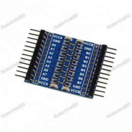
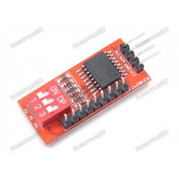
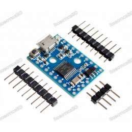
Module can be used to expand the digital I/O of an MCU using the I2C bus.
 Store Pickup Available!
 Free Ship Over 5000 BDT
 Quality Product
 No Warranty
 No Replacement
The PCF8574 module can be used to expand the digital I/O of an MCU using the I2C bus.
A common requirement when working with MCUs is the need to add more digital I/O than the device supports natively. The PCF8574 is one of the more popular methods of adding lines as it uses the I2C bus that requires only 2 lines on the MCU. It provides 8 additional digital I/O lines which are easily expandable up to 64.
The module has an easy to use I2C interface that can be configured to use any one of eight different I2C addresses if you want to use multiple modules in the same system or if you run into an address conflict with another device.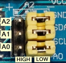
The base I2C address of the modules is 0x20.
There are three address jumps (A0-A2) the determines which I2C address to use. As shipped, these jumpers are all set to the ‘-‘ side which is ground or LOW as shown in the picture. The ‘+’ side is Vcc or HIGH.
This puts the module at the base address of 0x20. The jumpers can be moved in a binary fashion to increase the address, so the address can range from 0x20 to 0x27 as shown in the table below.
If you daisy-chain the modules, you will need to set a different address for each of the modules.
| Address (Hex) | A2 | A1 | A0 |
| 0x20 | LOW | LOW | LOW |
| 0x21 | LOW | LOW | HIGH |
| 0x22 | LOW | HIGH | LOW |
| 0x23 | LOW | HIGH | HIGH |
| 0x24 | HIGH | LOW | LOW |
| 0x25 | HIGH | LOW | HIGH |
| 0x26 | HIGH | HIGH | LOW |
| 0x27 | HIGH | HIGH | HIGH |
You may run into devices with the PCF8574A part installed. If that happens, don’t panic. These just use a different starting I2C address of 0x38. This part is offered by the mfr so that if both A and non-A parts are used together in a system, the number of modules can be increased up to a maximum of 16 providing at total of 128 digital lines. The ‘T‘ marking on the devices just denote that it is a surface mount device.
If there is ever a doubt about the I2C address of this or any device, just hook it up to the I2C bus and apply power and ground and then run the I2C scanner software.
The I/O is defined as quasi-bidirectional. A quasi-bidirectional I/O is either an input or output port without using a direction control register. When set as inputs, the pins act as normal inputs do. When set as outputs, the PCF8574 device drives the outputs LOW with up to 25mA sink capability but when driving the outputs HIGH, they are just pulled up high with a weak internal pull-up. That enables an external device to overpower the pin and drive it LOW.
The device powers up with the 8 data lines all set as inputs.
When using the pins as inputs, the pins are set to HIGH by the MCU, which turns on a weak 100 uA internal pull-up to Vcc. They will read as HIGH if there is no input or if the pin is being driven HIGH by an external signal but can be driven LOW by an external signal that can easily override the weak pull-up.
If used as outputs, they can be driven LOW by the MCU by writing a LOW to that pin. A strong pull-down is turned on and stays on to keep the pin pulled LOW. If the pin is driven HIGH by the MCU, a strong pull-up is turned on for a short time to quickly pull the pin HIGH and then the weak 100uA pull-up is turned back on to keep the pin HIGH.
If the pins are set to be outputs and are driven LOW, it is important that an external signal does not also try to drive it HIGH or excessive current may flow and damage the part.
Whenever the internal register is read, the value returned depends on the actual voltage or status of the pin.
The I/O ports are entirely independent of each other, but they are controlled by the same read or write data byte.
The interrupt open drain output pin is active LOW. It is normally pulled HIGH using a pull-up resistor and is driven low by the PCF8574 when any of the inputs change state. This signals the MCU to poll the part to see what is going on. If connecting this pin, enable the internal pull-up resistor on the MCU or add an external pull-up of 10K or so.
If using interrupts with multiple modules, since they are open drain they can be tied together if a single interrupt back to the MCU is desired.
The connections to the module are straight forward.
1 x 4 Header (Male & Female)
1 x 9 Header
These modules are useful for expanding digital I/O.
One thing to keep in mind is that since the device has strong drive (25mA) when sinking current, but low drive (300uA) when sourcing current, it is best to drive LEDs and similar devices that require higher current by tying their anode to Vcc and pulling their cathode LOW with the PCF8574. A current limiting resistor is generally required.
The example program below sets up all 8 lines as inputs and writes a HIGH to them to enable the weak internal pullups of the PCF8574, so these pins will read HIGH unless something drives them low.
Pushbuttons with one side grounded can be connected to these inputs. The MCU which then scans the PCF8574 inputs and prints out any button found to be pressed.
The example here uses the xreef/pcf8574 library that can be downloaded from GitHub: https://github.com/xreef/PCF8574_library
/*
   This example for the PCF8574 takes pushbutton inputs on pins 0-7 and
   sends the number of the button pressed to the Serial Monitor window.
   Pins are normally HIGH and pulled LOW when button is pressed.

   Uses the xreef/PCF8574.h library
*/
#include "Arduino.h"
#include "PCF8574.h"

PCF8574 pcf8574(0x20);  // Set (I2C address)

//===============================================================================
//  Initialization
//===============================================================================
void setup()
{
 Serial.begin(9600);

 for(int i=0;i<8;i++) {
    pcf8574.pinMode(i, INPUT);    // Set all pins as inputs
    pcf8574.digitalWrite(i,HIGH); // Enable weak pull-ups to pull pins HIGH
  }
  pcf8574.begin();
  delay(500);  // Give the pcf8574 a little time to initialize
}
//===============================================================================
//  Main
//===============================================================================
void loop()
{ // just loop scanning the keys
   if (pcf8574.digitalRead(P0)==LOW) {Serial.println("KEY 0");}
   if (pcf8574.digitalRead(P1)==LOW) {Serial.println("KEY 1");}
   if (pcf8574.digitalRead(P2)==LOW) {Serial.println("KEY 2");}
   if (pcf8574.digitalRead(P3)==LOW) {Serial.println("KEY 3");}
   if (pcf8574.digitalRead(P4)==LOW) {Serial.println("KEY 4");}
   if (pcf8574.digitalRead(P5)==LOW) {Serial.println("KEY 5");}
   if (pcf8574.digitalRead(P6)==LOW) {Serial.println("KEY 6");}
   if (pcf8574.digitalRead(P7)==LOW) {Serial.println("KEY 7");}
   delay(250);
}
The latest price of PCF8574 I2C I/O Expansion Module in Bangladesh is BDT 160 You can buy the PCF8574 I2C I/O Expansion Module at best price from our RoboticsBD or visit RoboticsBD Office.
|
Please note that the product information provided on our website may not be entirely accurate as it is collected from various sources on the web. While we strive to provide the most up-to-date information possible, we cannot guarantee its accuracy. We recommend that you always read the product labels, warnings, and directions before using any product. |
|
Product Images are shown for illustrative purposes only and may differ from the actual product. |
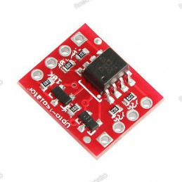
Reference: RBD-1368
Voltage level: 1.8V-6V Dimension: 38mm x 31.6mm Conversion level range: 1.8 V-6 V Instructions for use: (3.3 V, 5 V to each other) 4 pairs of power supply interfaces, supports more situation Use tantalum capacitors for power filter, provides more stability VCCB 5V power supply (can be an external 5V power supply)
Reference: RBD-2078
No direction, any angle can trigger the work. Sensitivity switches can be selected for the trigger sensitivity according to circuit requirements. This switch is suitable for the trigger of the small current circuit. Component Type: SW-18015P Maximum voltage: 12V Rated Heating Current: 20mA
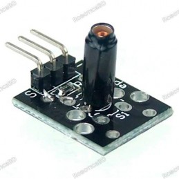
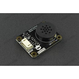
Reference: RBD-1970
Brand: DFRobot
Version 2.0 More natural pronunciation Fewer pronunciation errors for polyphone characters No option of speakers
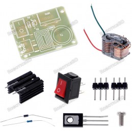
Reference: RBD-2296
Features:This product is a booster coil production suite, the circuit is simple and reliable, with professional line drawings, electronic research convenience enthusiastsUses: high school science experiment, electronic equipment, negative ion generator, scientific small production. This circuit is generated when the stable high-frequency arc, elevated...
Reference: RBD-1928
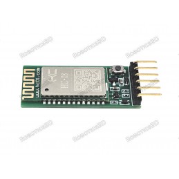
Frequency: 2.4GHz ISM. Protocol: BLE 4.0. Max transmitting power: max. 4dBm. Modulation System: GFSK. Serial Baud Rate: 1200 to 115200 bps. Reference Distance: 80 meters.
Reference: RBD-1065
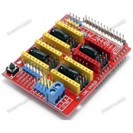
Latest Arduino CNC Shield Version 3.10 GRBL 0.9 compatible. (Open source firmware that runs on an Arduino UNO that turns G-code commands into stepper signals) Coolant enable Jumpers to set the Micro-Stepping for the stepper drivers. (Some drivers like the DRV8825 can do up to 1/32 micro-stepping ) Compact design. 4-Axis support (X, Y, Z, A-Can duplicate...
Reference: RBD-2735
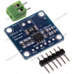
Measures high-side current and voltage up to 3.2A @ 26VDC.
Reference: RBD-0419
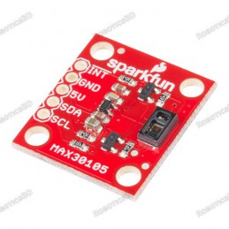
Features: Built-in Red, IR, and Green LEDs 5V operation (3.3V is allowed, but green LED is not guaranteed to operate) Applications include presence detection, distance sensing (18" max), pulse oximetry, blood oxygen saturation level (SpO2), smoke and particle detection Documents: Schematic Eagle Files Hookup Guide Datasheet (MAX30105) MAX3010x Sensor...
Reference: RBD-2447
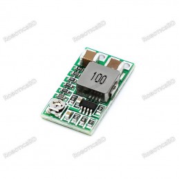
Ultra small module converts 4.5 – 24V input down to a 0.8 – 22V output @ up to 2A.
Reference: RBD-1098
Interface: I2C Operating Voltage: 3-5VDC Ports: 8-bit Parallel Ports Can be used with Arduino and Raspberry Pi
Reference: RBD-0981
Low power device. DTMF decoder chip. Band-split filter. Digital decoding functions. Modem interfaces. Mobile radios.
Reference: RBD-1911
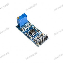
LM358 chip onboard. 100 gain of the circuit design. 10K onboard adjustable resistance, you can adjust the magnification. Onboard power indicator. The chip has led major pin can be directly input and output signals.
Reference: RBD-1809
Digispark Pro ATtiny167 Micro USB 16MHz
Reference: RBD-0393
Dimensions: 40 x 27 x 15 (LxWxH) mm. RoboticsBD Weight: 10gm (without Hat). 2.54mm pin interface leads. Operating Voltage: 5V. Long service life and stable performance. Standard interface and electronic building blocks. Widely use in Arduino DIY projects. RoboticsBD
Reference: RBD-2542
Brand: DFRobot
This is an SIM808 GSM/GPRS/GPS IoT Board based on Arduino Leonardo. The SIM808 with Leonardo mainboard is the latest development board for multi-purpose applications. The onboard SIM808 module includes an integrated quad-band GSM/GPRS and GPS satellite navigation module, and a 4 layer PCB integrates the microcontroller, microphone, headphone jack and...
Reference: RBD-2725
Onboard LM386 Chip. 200 multiplier benefits circuit design. On-board speaker wiring Block. On-board 10K variable resistor, you can adjust the volume of the enlarged. Onboard power indicator.
Reference: RBD-2761
ICL8038 12V to 15V, Signal Generator, Medium/Low Signal, Frequency 10Hz-450KHz, Triangular/Rectangular/Sine Wave Generator, Module Working voltage: 12V ~ 15V Output: Triangular wave, Square wave and sine wave. Frequency range: 10HZ ~ 450kHz Low distortion sine wave: 1% Duty cycle range: 2% to 98% Low temperature drift: 50ppm / ℃ Triangular wave output...
Reference: RBD-2489
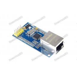
Wiznet Compact W5500 Network Module - 10/100 Base T WIZ850io is a compact size network module that includes a W5500 (TCP/IP hardwired chip and PHY embedded), a transformer and RJ45. It can be used as a component and no effort is required to interface W5500 and Transformer. The WIZ850io is an ideal option for users who want to develop their Internet...
Reference: RBD-0579
Quad-band 850/900/1800/1900MHz GPRS multi-slot class12 connectivity: max. 85.6kbps(down-load/up-load) GPRS mobile station class B Controlled by AT Command (3GPP TS 27.007, 27.005 and SIMCOM enhanced AT Commands) Supports charging control for Li-Ion battery Supports Real-Time Clock Integrated GPS/CNSS and supports A-GPS Low power consumption, 10mA in sleep...
Reference: RBD-2077
Operating Voltage:2.0v ~ 2.5v Current:10mA Diameter:3mm Wavelength:571nm + 644nm Beam Angle:150
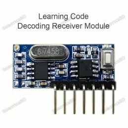
Reference: RBD-2134
433Mhz Wireless Receiver Learning Code EV1527 Decoding Module 4-channel output with a learning button Compatible with Arduino/ARM/MCU Ideal for wireless power switch sockets, remote controls, LED lighting, and electric doors Wide range of applications in home automation, security systems, and remote control devices
Reference: RBD-2065
Play standard mono or stereo MP3 files Control with buttons Serial communications protocol (JQ6500 Arduino Library available). Power supply 4.2V Speaker power 4 ohms / 3 watts
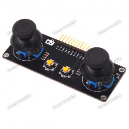
Reference: RBD-2291
Functional configuration: 2 PS2 game joysticks (2 analog voltages per channel) 1 digital level) 2 independent buttons (original button) Product Features: The X and Y axes output are two potentiometers, and the twist angle can be read by AD conversion. Press the rocker down to send a touch switch, for digital output, has been pulled up Original Omron...
Reference: RBD-1381
Forward voltage 1.55V Reverse current 100mA Capacitance 25 pF
Reference: RBD-2720
Chip type: W5500. Supports both 3.3V & 5V. Support Hardwired TCP/IP Protocols: TCP, UDP, ICMP, IPv4, ARP, IGMP, PPPoE. 10BaseT/100BaseTX Ethernet PHY embedded. Supports automatic response (full duplex/half duplex mode). Internal 32Kbytes Memory for Tx/Rx Buffers.
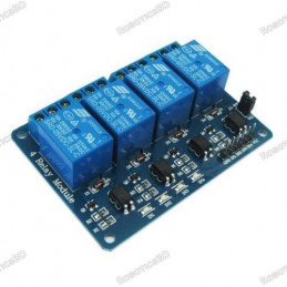
Reference: RBD-0409
No. of Channel: 4 Trigger Voltage: 5VDC Triode drive, increasing relay coil High impedance controller pin Pull-down circuit for the avoidance of malfunction Power supply indicator and Control indicator lamp Power supply and relay instructions, lit, the disconnect is off; The input signal, signal, common Terminal and start conducting; RoboticsBD Note:...
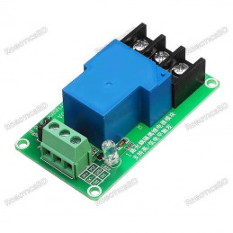
Reference: RBD-2658
This 1 channel 12V 30A relay control board module with optocoupler modules is compliant with international safety standards, control and load areas isolation trenches it has a single relay a genuine. The inputs of 1 Channel 12V 30A Relay Module are isolated to protect any delicate control circuitry. It can be used as a single chip module for appliance...
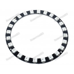
Reference: RBD-2304
This is the 24 LED NeoPixel Ring, a small chainable 86mm outer diameter board equipped with 5050 WS2812 RGB LEDs. The WS2812s are each addressable as the driver chip is located inside the LED. Each NeoPixel Stick has ~18mA constant current drive so the color will be very consistent even if the voltage varies, and requires 5 V.
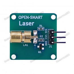
Reference: RBD-2558
This is a mini Laser light module with onboard triode current amplifier circuit, it gets only 1.3mA from the SIG pin so it is compatible with much more MCU. Note: For safe use, the module must not directly illuminate human eyes or irradiate human body for a long time. Features: - Output wavelength: 650nm - Working voltage: 4.75-5.5V - Working current:...
Module can be used to expand the digital I/O of an MCU using the I2C bus.