Reference: RBD-1354
Jumper Wire Single 20cm
Length: 8 inches/20 CM (Long) Material: Copper Plated Pin Spacing: 2.54mm.
Reference: RBD-1354
Length: 8 inches/20 CM (Long) Material: Copper Plated Pin Spacing: 2.54mm.
Reference: RBD-0351
Contactless transmission of data and supply energy (no battery needed) Operating distance: Up to 100mm (depending on antenna geometry) RoboticsBD Operating frequency: 13.56MHz Data transfer: 106 kbit/s Data integrity: 16 Bit CRC, parity, bit coding bit counting Anticollision Typical ticketing transaction: <100 ms ( including backup management)...
Reference: 0245
Choose your desire Resistor value from below:
Reference: 0031
3 Types Available (Please select from option) 1. Male to Male 2. Male to Female 3. Female-Female
Reference: RBD-0768
Size: 5mm Color: RED Head Shape: Round Lens Appearance: Transparent
Reference: RBD-0761
Breadboard friendly Mounting Style: Through Hole Mounting Direction: Vertical
Reference: 1353
Length: 12.5 inches/30 CM (Long) Material: Copper Plated Pin Spacing: 2.54mm.
HW-827 Pulse Sensor 3.3-5V Heartbeat Heart Rate Monitor Sensor
Easy to use finger-tip heart rate detector module with built-in noise filter and signal amplification.
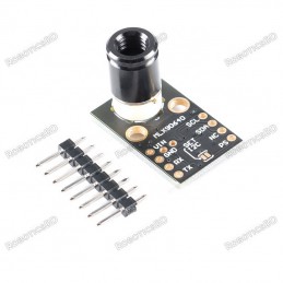
The PulseSensor Heart Rate Sensor is an easy to use finger-tip heart rate detector module with built-in noise filter and signal amplification.
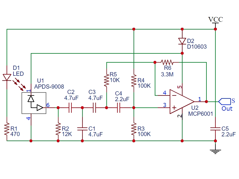
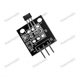
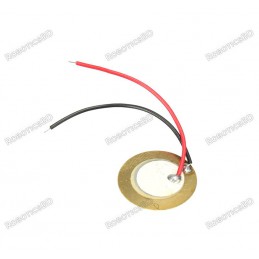
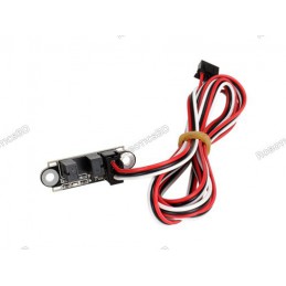
If you look closely at the module, you will see a small photosensor on the front side with the silk-screened heart where you place your finger.
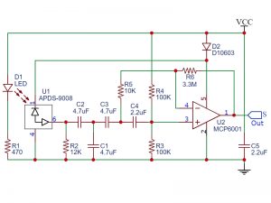
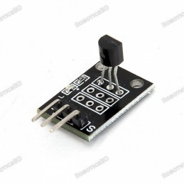
On the backside of the module you will find the rest of the components including a reverse mounted green LED that shines through the hole, an Op Amp and a number of resistors and capacitors and a diode.
The sensor works by shining a bright green LED into a finger (or other body part like an ear lobe) and detecting the amount of light that is reflected back used a photosensor that is tuned to the green light spectrum.
As blood is pumped through the finger with each heartbeat, the amount of reflected light changes, creating a changing waveform on the output of the photosensor that is representative of the heart rate.
This signal from the photosensor is small and riding on a changing DC bias, so the signal is then passed through an R/C filter network and then amplified using an Op Amp to create a signal that is much larger, cleaner and easier to detect using an analog port on an MCU.
The wire colors are not color coded, so ensure that you look at the markings on the back of the module to ensure that you have the three wires correctly identified
The module can be powered from 3.3 or 5V. The positive voltage connects to ‘+’ and ground connects to ‘-‘. There is a reverse protection diode on the module to prevent damage should the power leads be accidentally reversed.
The 3rd ‘S’ wire is the analog signal output from the sensor and this will connect to the analog input of a uC.
1 x 3 Wire Harness
This device is a small unprotected circuit board which works fine for bench top testing and experimenting with heart rate detection. If you intend instead to use it for a more real-world application such as making a heart rate monitor to use while you are riding an exercise bike, you should plan to provide some protection to the module from salty sweat which can corrode and short circuit the circuitry as well as strain relieve the wires to prevent them from breaking from being constantly flexed.
Since the sensor comes with short breadboard style wires, you may need to replace them with longer wires that are more suitable for you application. You will want to do this before you seal the back of the unit as noted below.
The back of the module can be protected using hot melt glue. To apply, simply apply a glob of hot melt glue on something like blue painters tape and then press the back of the module into the hot glue. The hot melt glue also helps to strain relieve the wires if some is also dabbed on the front side of the wires as well. Once cool, remove from the tape and trim the excess glue from around the edges using nail trimmers or a similar tool.
The nice thing about hot melt is that it can be removed if you decide to make changes, but more permanent sealers like epoxy or RTV can also be used. Just be sure to use non-corrosive types that are compatible with electronics.
The front of the module can be protected using a transparent self adhesive vinyl sticker or similar. You should check performance before and after applying any protective layer over the LED and sensor to make sure the performance is not too greatly affected.
While the device is not quite hospital grade, it does a respectable job and is a big improvement over using the simple modules that include just an LED and photosensor.
The PulseSensor is an open source device originally created by PulseSensor.com. There is a wealth of information available on their website. If you download the PulseSensor Playground library in the Arduino IDE, it will also install a number of sample programs that can be used with the sensor.
The simple program below reads the sensor and blinks the on-board LED each time it detects a pulse. It does not require an library, it simply reads the output of the sensor directly and blinks the LED if the reading is above or below a threshold value.
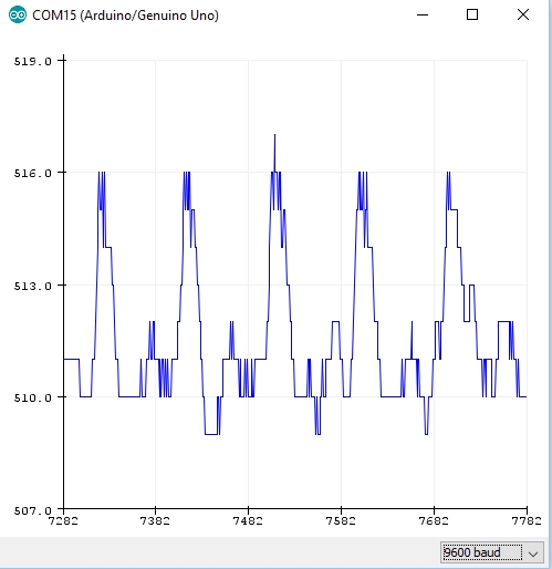
More interestingly, you can open the Serial Plotter window which will plot the output of the sensor so that you can see how the position of the finger and pressure affects the reading.
To get it running, simply hook the sensor up to 5V and ground and connect the Signal pin to A0. Place your finger on the sensor and give it a few moments for the plotter window to autoscale and basically zoom in on signal. You will find that finger position and amount of pressure will have a significant affect on the reading. Generally you want just a light pressure on the sensor.
An example Serial Plotter window output reading is shown here to the right. In this case, the pulse is registering between about 510 and 516. If you are powering the sensor off of 5V, the default threshold setting of 512 will get you close but you may want to play with that value for best detection. You can look at the Y-Axis of the serial plotter graph to see the range of numbers that the sensor is providing and adjust the threshold value based on that to give the best pulse detection.
If you wanted to determine the pulse rate, you could count the milliseconds between the detected pulses and calculate it from the formula Pulse Rate = 60 / (milliseconds/1000)
/* PulseSensor Heart Rate Test Program * Basic code to evaluate the PulseSensor heart rate sensor module * Connect to 5V, Gnd and Signal goes to A0 * * When heartbeat detected, flash on-board LED * Open Serial Plotter window to observe the detected waveform. * Threshold value can be adjusted for best detection. */ int const PULSE_SENSOR_PIN = 0; // 'S' Signal pin connected to A0 int Signal; // Incoming ADC data. Value can range from 0-1024 int Threshold = 512; // Sets ADC threshold for what constitutes a heartbeat. //=============================================================================== // Initialization //=============================================================================== void setup() { pinMode(LED_BUILTIN,OUTPUT); // Built-in LED will blink to your heartbeat Serial.begin(9600); // Set comm speed for serial plotter window } //=============================================================================== // Main //=============================================================================== void loop() { Signal = analogRead(PULSE_SENSOR_PIN); // Read the sensor value Serial.println(Signal); // Send the Signal value to Serial Plotter if(Signal > Threshold){ // If the signal is above threshold,turn on LED digitalWrite(LED_BUILTIN,HIGH); } else { digitalWrite(LED_BUILTIN,LOW); // Else, if signal below threshold, so turn off LED } delay(10); }
The latest price of HW-827 Pulse Sensor 3.3-5V Heartbeat Heart Rate Monitor Sensor in Bangladesh is BDT 297 You can buy the HW-827 Pulse Sensor 3.3-5V Heartbeat Heart Rate Monitor Sensor at best price from our RoboticsBD or visit RoboticsBD Office.
Please note that the product information provided on our website may not be entirely accurate as it is collected from various sources on the web. While we strive to provide the most up-to-date information possible, we cannot guarantee its accuracy. We recommend that you always read the product labels, warnings, and directions before using any product. |
Product Images are shown for illustrative purposes only and may differ from the actual product. |
Reference: RBD-2073
Digital Output Hall-effect sensor. Operating voltage: typically 5V. Output Current: 25mA. It can be used to detect both the poles of a magnet.
Reference: RBD-2482
Module utilizes the popular 1-Wire DS18B20 temperature measurement IC.
Reference: RBD-0355
Description:Working voltage: 4.5V to 5.5 V.Transmit tube pressure drop: Vf = 1.6 VTransmit tube current: 20 mASignal output: A, B two way; The TTL levelDistinguish precision: 0.01 mmMeasurement frequency, 100 KHZEncoder diameter: 24 mmEncoder type D hole diameter: 4 mmThe encoder resolution: 20 line
Reference: RBD-1717
Wide voltage operation: 3.3~5.5V 0~2.3V analog signal output, compatible with 5V, 3.3V two control systems The excitation source is an AC signal, effectively preventing probe polarization Waterproof probe for long-term immersion in water
Reference: RBD-1699
Brand: SparkFun Electronics
Simple switches Detect a collision SPST switch
Reference: RBD-2385
Module for measuring infrared temperature Uses the GY-MCU90640 MLX90640 BAA 32*24 dot matrix sensor Field of view angle of 55*34 degrees Ambient temperature range of -40 to 85 degrees Target temperature range of -40 to 300 degrees Serial output frequency supports up to 16HZ baud rate 460800
Reference: RBD-2098
Big Microphone Sound Sensor Module Sound Detection Sensor Module High Sensitive Voice Sensor
Reference: RBD-0958
Five Operating Modes Integrated MCU Onboard Processing Standard I2C Digital Interface Optimized Low-Power Modes Optional NTC Thermistor Pins
Reference: RBD-1193
Infrared Photodiode Transmitter 3mm Infrared Photodiode Receiver 3mm
Reference: RBD-1675
Model: PZEM-004T Operating Voltage: 80-260VAC Test Voltage: 80-260VAC Rated Current: 100A Rated power: 100A / 22000W Operating frequency: 45-65Hz Measurement accuracy: 1.0
Reference: RBD-1654
5 In 1 Portable CO2 Detector Air Quality Detector Intelligent Air Detector Temperature and Humidity Sensor Carbon Dioxide Monitor TVOC Formaldehyde Detection HCHO Detector Color Black
Reference: RBD-1727
This is 38KHz Infrared IR transmitter sensor module For Arduino Transmit 38KHz modulating signal Suitable for Arduino DIY project Material: PCB
Reference: RBD-2114
Multifunctional Expansion Board LM35 Temperature Buzzer for Arduino UNO Fully compatible with Arduino UNO interface Integrates multiple module functions Provides basic experimental modules for beginners Expansion ports for additional module experiments
Reference: RBD-0222
Sound pressure level: 85DB 10cm The input voltage: 30vp-p max Ultra-thin and lightweight Low power consumption for voltage type Operating Temperature: -20~70 Storage Temperature: -30-80 Clear sound
Reference: RBD-2303
LED peak wavelength: 660nm/880nm LED power supply voltage: 3.3~5V Detection signal type: light reflection signal (PPG) Output signal interface: I2C interface
Reference: RBD-0695
Integration Lowers System Cost, Simplifies Design Efforts, and Reduces Design Cycle Time High Accuracy Facilitates Meeting Error Budgets 15-Bit ADC Resolution; Nominal Temperature Resolution 0.03125NC (Varies Due to RTD Nonlinearity) Total Accuracy Over All Operating Conditions:
Reference: RBD-2364
Pyroelectric Infrared Sensor Human Body Detecting PIR Motion Sensor Module for Arduino MCU 011050 Black Optical Lens
Reference: RBD-1671
ESP32 Bluetooth Wi-Fi development board, support NodeMCU / Arduino DHT11 temperature and humidity sensor CP2104 communication chip USB TO TTL Micro USB port Soil probe (long) soil temperature and humidity detection module 18650 Lithium Battery Holder Powered (Battery is not included)
Reference: RBD-2339
The AM312 is an ultra-miniature PIR module that uses a pyroelectric sensor similar to the one found in the common SR501 but in a more compact form factor.
Reference: RBD-0664
Supply Voltage: 3.3 V/ 5V. Interface Type: I²C, SPI. Sensing Range: ±2g, ±4g, ±8g, ±16g. Sensitivity X: 28.6 LSB/g. Sensitivity Y: 31.2 LSB/g. Sensitivity Z: 34.5 LSB/g. Ultra Low Power: 40µA in measurement mode, 0.1µA in standby@ 2.5V. Free-Fall Detection. Tap/Double Tap Detection. RoboticsBD
Reference: RBD-2444
Designed for use as an endstop for 3D printers but it can be used for other IR beam interrupter purposes as well.
Reference: RBD-2122
Working Voltage:1.8 to 5.5 V Shutdown Current:0.7µA Color:Green
Reference: RBD-0672
Power requirements: 5 VDC @ ~165 mA (heater on) / ~60 mA (heater off). Current Consumption: 150mA. RoboticsBD DO output: 0.1 and 5V. AO output: 0.1- 0.3 V (relative to pollution), the maximum concentration of a voltage of about 4V Detecting Concentration: 0.05-10mg/L Alcohol.
Reference: RBD-1833
NEW TYPE AVAILABLE CLICK HERE Measurement range: 0-199 mg/KG Measurement accuracy: +-2%F.s Resolution: 1mg/KG (mg/L) Response time (T90, s): less than 10 Communication port: RS485 Power supply: 5V-24v DC
Reference: RBD-2543
The LPB40B Single-Point Ranging LiDAR based on the DToF principle. The DToF technology enables the laser radar to work stably under strong outdoor lighting, further improving the stability and accuracy of distance measurement. It is capable of withstanding up to 100klux of ambient light, with a range of up to 40m indoors and outdoors. The overall accuracy...
Reference: RBD-1866
High Sensitivity PIR Sensor 360 Degree IR Infrared Motion Sensor Light Switch AC 110V-240V Ceiling Recessed PIR Switch Detector
Reference: RBD-1512
LDR 10 mm Light Depending Resistor Low-cost sensor device Wide spectral response Use in fire alarms, smoke alarms, control street light Low cost. Ambient Temperature Range. Wide spectral response.
Reference: RBD-0313
Low power consumption, Low cost, and Compact size Read and write chip Fully integrated at 13.56MHz
Reference: RBD-1687
Model No.: ISR18650-1300 Capacity (mAh): 750-1300 (Copy) Output Voltage: 3.7V High energy density High working voltage for single battery cells. It's a clone battery so the ampere couldn't be guaranteed.
Reference: RBD-0376
Current Sense for each motor. RoboticsBD Heatsink for better performance. Power-On LED indicator. Double H bridge Drive Chip: L298N. Operating Voltage(VDC): 5~35 Peak Current (A): 2 Continuous Current (A): 0-36mA No. of Channels: 2 Over-Current Protection (A): Yes Thermal Protection: Yes
Reference: RBD-1407
Flash LED off: 180mA @ 5V. Flash LED on to maximum brightness: 310mA @ 5V. Deep-sleep: 6mA @ 5V min. Modem-sleep: 20mA @ 5V min. Light-sleep: 6.7mA @ 5V min. Programmer: ESP32-CAM-MB MICRO USB Download Module The ESP32 CAM does not come pre-assembled with the camera. You'll need to connect the camera ribbon cable to the board, a task which can be...
Reference: RBD-0433
5V power supply. Serial I2C control of LCD display using PCF8574. RoboticsBD Backlight can be enabled or disabled via a jumper on the board. Contrast control via a potentiometer. Can have 8 modules on a single I2C bus (change address via solder jumpers)address, allowing.
Reference: RBD-1213
Battery Charger for 2*18650 Rechargeable Li-Ion Batteries Suitable for 2*18650 rechargeable Li-Ion batteries Input: AC 100-240V/50-60Hz 200mA max Output: DC 4.2V 1000mA*2
Reference: RBD-1354
Length: 8 inches/20 CM (Long) Material: Copper Plated Pin Spacing: 2.54mm.
Reference: RBD-2639
Connect components on breadboards and PCBs easily. 20 pre-crimped jumper wires for versatile use. 20cm length for convenient connections. Male-to-male connector design for simple use. Colorful for easy identification and organization.
Reference: RBD-2640
Connect components on breadboards and PCBs with ease. 20 pre-crimped jumper wires for versatile use. 20cm length for convenient connections. Male-to-female connector design for flexible connections. Colorful for easy identification and organization.