
- On sale!

How to Place an Order

Store Pick Up

Request for Quotation/ International Sourcing

Order Status

Reference: RBD-1354
Length: 8 inches/20 CM (Long) Material: Copper Plated Pin Spacing: 2.54mm.
Reference: RBD-0351
Contactless transmission of data and supply energy (no battery needed) Operating distance: Up to 100mm (depending on antenna geometry) RoboticsBD Operating frequency: 13.56MHz Data transfer: 106 kbit/s Data integrity: 16 Bit CRC, parity, bit coding bit counting Anticollision Typical ticketing transaction: <100 ms ( including backup management)...
Reference: 0245
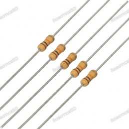
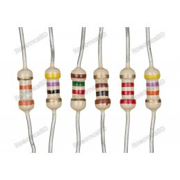
Choose your desire Resistor value from below:
Reference: 0031
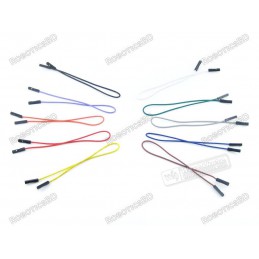
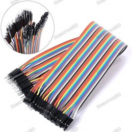
3 Types Available (Please select from option) 1. Male to Male 2. Male to Female 3. Female-Female
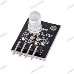
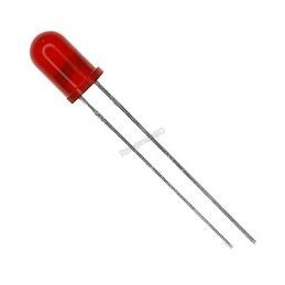
Reference: RBD-0768
Size: 5mm Color: RED Head Shape: Round Lens Appearance: Transparent
Reference: RBD-0761
Breadboard friendly Mounting Style: Through Hole Mounting Direction: Vertical
Reference: 1353
Length: 12.5 inches/30 CM (Long) Material: Copper Plated Pin Spacing: 2.54mm.


 Store Pickup Available!
 Free Ship Over 5000 BDT
 Quality Product
 No Warranty
 No Replacement
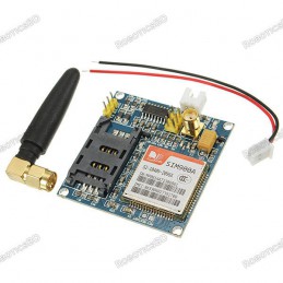
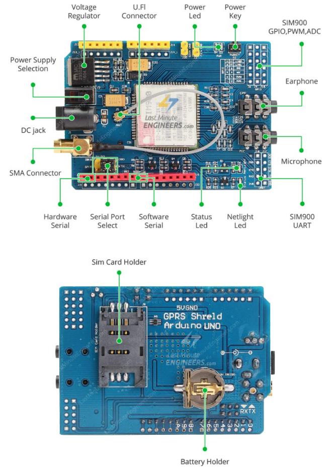
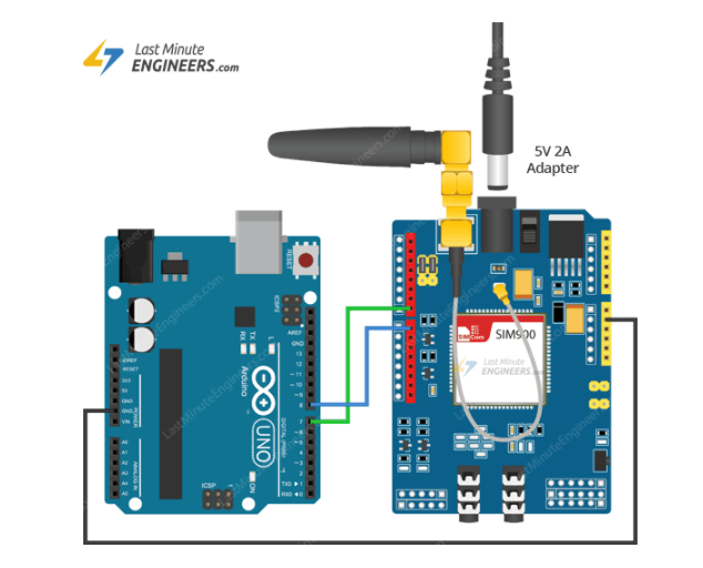
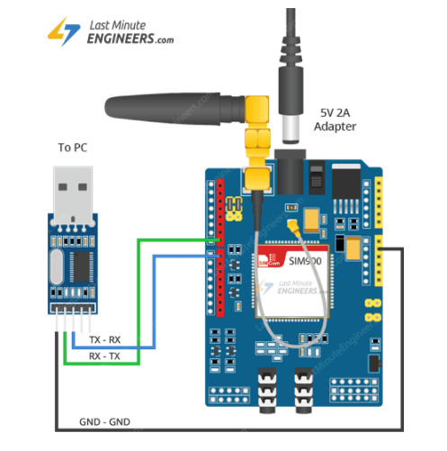
SIM900 GSM/GPRS shield is a GSM modem, which can be integrated into a great number of IoT projects. You can use this shield to accomplish almost anything a normal cell phone can; SMS text messages, Make or receive phone calls, connecting to internet through GPRS, TCP/IP, and more! To top it off, the shield supports quad-band GSM/GPRS network, meaning it works pretty much anywhere in the world.
The SIM900 GSM/GPRS shield is designed to surround the SIM900 chip with everything necessary to interface with Arduino, plus a few extra goodies to take advantage of the chip’s unique features. Featured By RoboticsBD.
Product Images are shown for illustrative purposes only and may differ from the actual product.
RoboticsBD RoboticsBD RoboticsBD RoboticsBD RoboticsBD RoboticsBD RoboticsBD RoboticsBD RoboticsBD RoboticsBD
Hardware Overview of SIM900 GSM/GPRS Shield
RoboticsBD RoboticsBD RoboticsBD RoboticsBD RoboticsBD RoboticsBD RoboticsBD RoboticsBD RoboticsBD RoboticsBD
| General Specification | |
| Model | Based on SIMCom‘s SIM900 Module |
| GSM networks | Quad-Band 850 / 900/ 1800 / 1900 MHz |
| Control | AT commands |
| GPIOs | 12 |
| Speaker and Headphone jacks | Yes |
| Shipment Weight | 0.05 kg |
| Shipment Dimensions | 12 × 8 × 2.5 |
Please allow 5% measuring deviation due to manual measurement.
RoboticsBD RoboticsBD RoboticsBD RoboticsBD RoboticsBD RoboticsBD RoboticsBD RoboticsBD RoboticsBD RoboticsBD
1 x GPRS GSM SIM900 Arduino Shield.
RoboticsBD RoboticsBD RoboticsBD RoboticsBD RoboticsBD RoboticsBD RoboticsBD RoboticsBD RoboticsBD RoboticsBD
RoboticsBD RoboticsBD RoboticsBD RoboticsBD RoboticsBD RoboticsBD RoboticsBD RoboticsBD RoboticsBD RoboticsBD
The latest price of GPRS GSM SIM900 Arduino Shield in Bangladesh is BDT 2,400 You can buy the GPRS GSM SIM900 Arduino Shield at best price from our RoboticsBD or visit RoboticsBD Office.
|
Please note that the product information provided on our website may not be entirely accurate as it is collected from various sources on the web. While we strive to provide the most up-to-date information possible, we cannot guarantee its accuracy. We recommend that you always read the product labels, warnings, and directions before using any product. |
|
Product Images are shown for illustrative purposes only and may differ from the actual product. |
 (7)
(7) (0)
(0) (0)
(0) (0)
(0) (0)
(0) (0)
(0)
Reference: RBD-0318
This module is intended for advanced users who require moderate knowledge of GSM systems and microcontrollers. It needs wiring and firmware updates to unlock the country lock. Dual-Band 900/ 1800 MHz GPRS multi-slot class 10/8GPRS mobile station class B Compliant to GSM phase 2/2+ Dimensions: 24*24*3 mm Weight: 3.4g Control via AT commands (GSM 07.07...
Reference: RBD-0579
Quad-band 850/900/1800/1900MHz GPRS multi-slot class12 connectivity: max. 85.6kbps(down-load/up-load) GPRS mobile station class B Controlled by AT Command (3GPP TS 27.007, 27.005 and SIMCOM enhanced AT Commands) Supports charging control for Li-Ion battery Supports Real-Time Clock Integrated GPS/CNSS and supports A-GPS Low power consumption, 10mA in sleep...
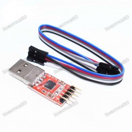
Reference: RBD-0658
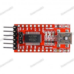
Standard interface layout, compatible with a variety of Arduinos such as the Pro Mini Original FTDI FT232 chip, stable performance USB power has current protection, using 500MA self-restore fuse RXD/TXD transceiver communication indicator With power, sending, receiving indicator, working status LED indicators Mini USB Port Connection Support 3.3V, 5V...
Reference: RBD-1037
Quad-band 850/900/1800/1900MHz Inner MT3337 GPS receiver, -165dBm precision, control on a same serial port. Earphone/ microphone outputs on a card or external 32-ohm speaker + supports voice calls with an electret microphone. Sending and receiving SMS.
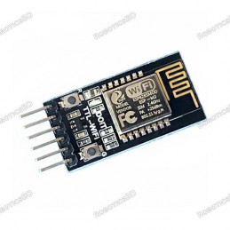
Reference: RBD-1578
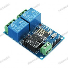
Support serial AT command Support re-programmable, OTA firmware update Seamless transparent transmission between serial and WiFi Built-in HTTP Web Server, support configure parameters by web page
Reference: RBD-1770
Brand new and high quality Included USB transceiver, without external circuit device With 3.3V and 5V dual power output With three LEDs: power indicator, data reception indicator, the data transmission indicator, working status Meets the USB2.0 specification requirements With self-recovery fuse. In the event of the accidental short circuit, it can...
Reference: RBD-1816
Anti-Interference Ability Baud rate: 110 ~ 256000bps Operating Voltage: 3v to 30VDC Compatible With Both 3V and 5V logic
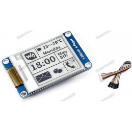
Reference: RBD-1759
Brand: Waveshare
Display Resolution: 200 x 200 Display Screen Color: Black and White No backlight so keeps displaying last content for a long time even when the power is down Ultra low power consumption, basically power is only required for refreshing SPI interface, for connecting with controller boards like Raspberry Pi/Arduino/Nucleo, etc.
Reference: RBD-0948
Built-in Flash: 32Mbit Power supply: 5V WiFi protocol: IEEE 802.11 b/g/n Peripheral interface: UART/GPIO/ADC/DAC/SDIO/PWM/I2C/I2S Logic level: 3.3V
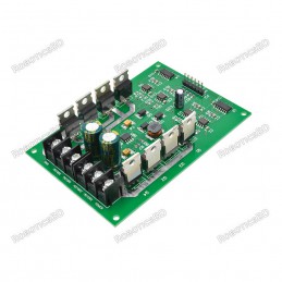
Reference: RBD-2308
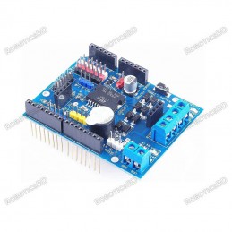
This Dual Dc motor driver focuses on high efficiency and can withstand high current load, the maximum current up to 30A.
Reference: RBD-2102
RGB trichromatic limiting resistor to prevent burnout PWM adjusted color mixing
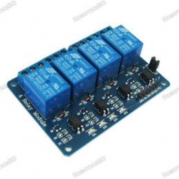
Reference: RBD-0409
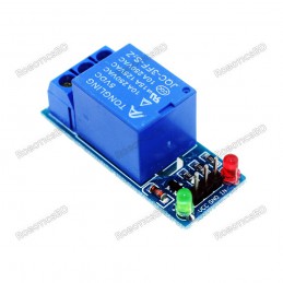
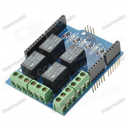
No. of Channel: 4 Trigger Voltage: 5VDC Triode drive, increasing relay coil High impedance controller pin Pull-down circuit for the avoidance of malfunction Power supply indicator and Control indicator lamp Power supply and relay instructions, lit, the disconnect is off; The input signal, signal, common Terminal and start conducting; RoboticsBD Note:...
Reference: RBD-0702
It has a relay status indicator led Power LED(Green), 8 relay status indicator LED(Red) Relay control interface by single-chip IO. Low-level suction close, high-level release. Easy to use, simple 3 line structure. Note: Relay might be different from the picture as per stock
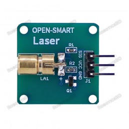
Reference: RBD-2558
This is a mini Laser light module with onboard triode current amplifier circuit, it gets only 1.3mA from the SIG pin so it is compatible with much more MCU. Note: For safe use, the module must not directly illuminate human eyes or irradiate human body for a long time. Features: - Output wavelength: 650nm - Working voltage: 4.75-5.5V - Working current:...
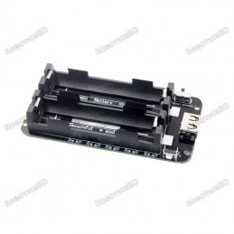
Reference: RBD-2208
2x 18650 Lithium Battery Shield V8 Mobile Power Expansion Board Module 5V/3A 3V/1A Micro USB for Arduino ESP32 ESP8266 Output port: USB or expansion port Output parameter 5V / 3A or 3.3V / 1A. Conversion efficiency up to 95% Input port: MicroUSB
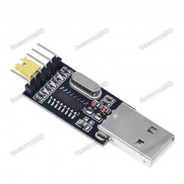
Reference: RBD-2362
Built-in USB to TTL Transfer chip. Designed to be used for USB to TTL electronic projects. TTL interface output, easy to connect to your MCU. Dual 3.3V and 5V Power output, work with 3.3v and 5 V target device. The mini-module is designed specifically for STC download and ARDUINO PRO supports all series of STC Supports WIN7/VISTA/MAC/LINUX(32 bit /64-bit...
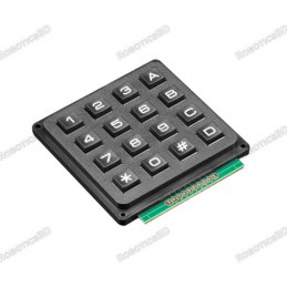
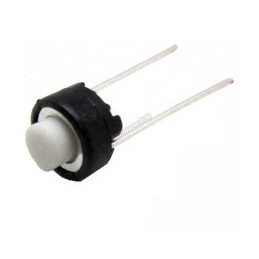
Reference: RBD-2156
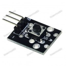
Easy communication with any microcontroller. Tactile type switches. Over 1,000,000 operations per key. Contact rated for 12V dc @ 20mA. Over 1,000,000 operations per key.
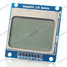
Reference: RBD-0399
Power supply voltage: 2.7 V-3.3 V/5 V Data interface level: 2.7-5V. Resolution: 84 x 48 pixel Backlight power supply voltage: highest 3.3 V. Backlight: Blue. RoboticsBD Note: Current stock is tested by us.
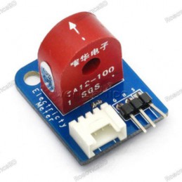
Reference: RBD-0564
Onboard precision microcurrent transformer. Onboard sampling resistor. The module can measure AC currents less than 5A, the corresponding analog output 5A/5mA. Rated input current: 5A Rated output current: 5mA Change: 1000: 1 The linear range: 0 ~ 10A (100 ohms) Linearity: 0.2%
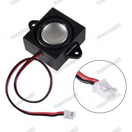
Reference: RBD-2470
3 Watt 8 Ohm Mini Speaker for Electronics Project with JST-PH2.0 Interface
Reference: RBD-2291
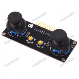
Functional configuration: 2 PS2 game joysticks (2 analog voltages per channel) 1 digital level) 2 independent buttons (original button) Product Features: The X and Y axes output are two potentiometers, and the twist angle can be read by AD conversion. Press the rocker down to send a touch switch, for digital output, has been pulled up Original Omron...
Reference: RBD-2305
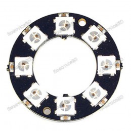
This is the 8 LED NeoPixel Ring, a small chainable 32mm outer diameter board equipped with 5050 WS2812 RGB LEDs. The WS2812s are each addressable as the driver chip is located inside the LED. Each NeoPixel Stick has ~18mA constant current drive so the color will be very consistent even if the voltage varies, and requires 5 V.
Reference: RBD-1180
Standard For Shield interfaces and shape Can continue to stack other For expansion boards 3 M3 screw positioning holes for easy installation High Drive (5V or 3.3V) normally open contact closure Onboard relay indicator (red) Note: Relay might be different from the picture as per stock
Reference: RBD-0987
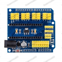
Compatible with Arduino NANO All digital and analog pins breakout Compact size; External power supply current support Leads all pins out, convenient for wiring and doing experiments.
Reference: RBD-2145
L298P based Arduino motor driver shield Onboard Buzzer (D4). Onboard Bluetooth interface, you can directly plug, no wiring required. Six Analog interface. Forward, Backward steering indicators
Reference: RBD-2442
8 channels can convert up to 8 logic signals Converts voltage levels between 1.2 to 3.6V and 1.65 to 5.5V systems Bi-directional with automatic direction control Each channel operates independently Optimized for open-drain applications like I2C, but can also work in push-pull applications Output enable allows outputs to be disabled
Reference: RBD-2296
Features:This product is a booster coil production suite, the circuit is simple and reliable, with professional line drawings, electronic research convenience enthusiastsUses: high school science experiment, electronic equipment, negative ion generator, scientific small production. This circuit is generated when the stable high-frequency arc, elevated...
Reference: RBD-2302
Low Standby Current. 1-to-8 Bidirectional Translating Switches. I2C Bus and SMBus Compatible. 5-V Tolerant Inputs. Latch-Up Performance Exceeds 100 mA Per JESD 78, Class II. Note : Product may vary in two variants TCA9548A & PCA9548A
Reference: RBD-2086
Operating Voltage: 5V Contact Resistance : 50mΩ max (initial) Electrically Life:100,000 cycles Environment temperature: -25°C to +105°C Operating Force: 180/230(±20gf) Seal temperature:250ºC-280ºC I/O pins: 3 pins
Reference: RBD-1337
Transmission Distance(m) :400 Relay Channel:2 Trigger Voltage (VDC): 5 Switching Voltage (VAC):250@10A Switching Voltage (VDC):30@10A Baud Rate:9600 Note: Relay might be different from the picture as per stock
Reference: RBD-1772
Small size package Local voice Customized voice wake-up/command words Universal Serial Port Protocol Support Chinese and English The number of command words reaches 150
Reference: RBD-2410
Retain the merits of the V4.0 version Laminated design PCB immersion gold processing technology IIC interface Bluetooth module communication interface SD card module communication interface APC220 wireless rf modules communication interface RB URF v1.1 ultrasonic sensors interface 12864 LCD string of line and parallel interface 32 servo controller interface
Reference: RBD-2323
The WS2812B RGB LED Module is a small module with BIG color. The module has a special LED on board that contains three separate LEDs – red, green, and blue – as well as a smart control IC that can individually drive each LED. Each color has 256 intensity levels which allows the module to produce 24-bit color, or more than 16 million colors. Each module...
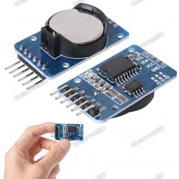
Reference: RBD-0386
1 Hz output pin SQW. 32 KHz output pin 32K. RoboticsBD Voltage Supply: 2.2 V ~ 5.5 V (for RTC). Time Format: HH: MM: SS (12/24 hr). Date Format: YY-MM-DD-dd. DS 3231 based RTC with 2032 Battery Holder. RoboticsBD Battery is not included Note: Batteries not included.
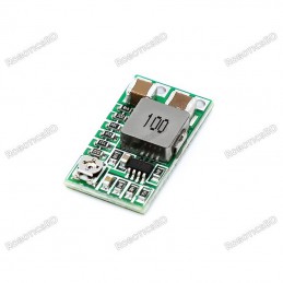
Reference: RBD-2447
Ultra small module converts 4.5 – 24V input down to a 0.8 – 22V output @ up to 2A.
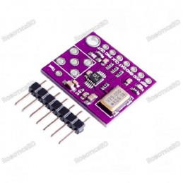
Reference: RBD-2228
Working voltage: 2.3V-5.5V. Working temperature range: -40 ~ + 105. Onboard 25MHZ (accuracy of 50ppm) active crystal. On-board high-speed amplifiers
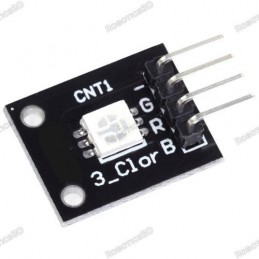
Reference: RBD-1367
RGB trichromatic limiting resistor to prevent burnout PWM adjusted color mixing Working voltage: 5V LED drive mode: Common cathode driver
Reference: RBD-0494
Input Voltage (V): 100 ~ 280 VAC @50 ~ 60Hz. Input current (mA): 100. Output Power: 12V 2A. Input Plug: 2-Pin USA type. Output Plug: 5.5mm DC plug. RoboticsBD Model: STD-120200
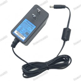
Reference: RBD-0313
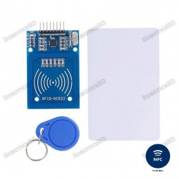
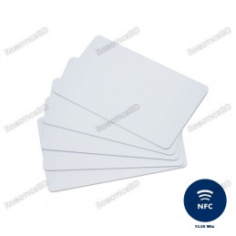
Low power consumption,Low cost, andCompact sizeRead and write chipFully integrated at 13.56MHz
Reference: RBD-0386
1 Hz output pin SQW. 32 KHz output pin 32K. RoboticsBD Voltage Supply: 2.2 V ~ 5.5 V (for RTC). Time Format: HH: MM: SS (12/24 hr). Date Format: YY-MM-DD-dd. DS 3231 based RTC with 2032 Battery Holder. RoboticsBD Battery is not included Note: Batteries not included.
Reference: RBD-0748
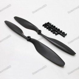
Length: 8″. Pitch: 4.5″. Weight: 20 gm. Shaft Diameter: 9.5mm. Total Length: 8 inch / 200 mm. It comes with a set of plastic reducers (3,3.17,4,5,6,8 mm).
Reference: RBD-0348
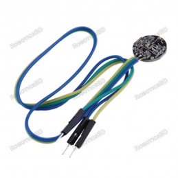
A Color-Coded Cable, with a standard male header connectors. Plug it straight into an Arduino or a Breadboard. No soldering is required. The Pulse Sensor has 3 holes around the outside edge which make it easy to sew it into almost anything. Visualization software (made in Processing) to instantly see the output of the sensor and for troubleshooting....
Reference: RBD-1371
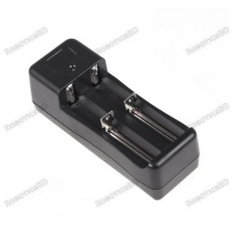
Input: AC 100-240V/ 47-63HZ Output: DC 3.7V/ 500mA Termination voltage: 4.2V+-1%
Reference: RBD-1172
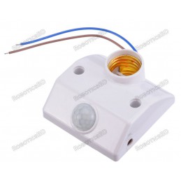
Infrared Sensor Automatic Lighting Control Switch with lamp holder; convenient, safe & practical. Good solution for energy saving. You can conveniently let the light auto on/off. The switch can detect the human body's infrared, and use infrared to control the load. Easy to install. Strong anti-interference ability Suitable for corridor, toilet,...
Reference: RBD-1180
Standard For Shield interfaces and shape Can continue to stack other For expansion boards 3 M3 screw positioning holes for easy installation High Drive (5V or 3.3V) normally open contact closure Onboard relay indicator (red) Note: Relay might be different from the picture as per stock