![TJA1050 CAN Bus Transceiver Module Robotics Bangladesh TJA1050 CAN Bus Transceiver Module Robotics Bangladesh](https://store.roboticsbd.com/7255-large_default/tja1050-can-bus-transceiver-module-robotics-bangladesh.jpg)
Reference: RBD-1354
Jumper Wire Single 20cm
Length: 8 inches/20 CM (Long) Material: Copper Plated Pin Spacing: 2.54mm.
Reference: RBD-1354
Length: 8 inches/20 CM (Long) Material: Copper Plated Pin Spacing: 2.54mm.
Reference: RBD-0351
Contactless transmission of data and supply energy (no battery needed) Operating distance: Up to 100mm (depending on antenna geometry) RoboticsBD Operating frequency: 13.56MHz Data transfer: 106 kbit/s Data integrity: 16 Bit CRC, parity, bit coding bit counting Anticollision Typical ticketing transaction: <100 ms ( including backup management)...
Reference: 0245
Choose your desire Resistor value from below:
Reference: 0031
3 Types Available (Please select from option) 1. Male to Male 2. Male to Female 3. Female-Female
Reference: RBD-0768
Size: 5mm Color: RED Head Shape: Round Lens Appearance: Transparent
Reference: RBD-0761
Breadboard friendly Mounting Style: Through Hole Mounting Direction: Vertical
Reference: 1353
Length: 12.5 inches/30 CM (Long) Material: Copper Plated Pin Spacing: 2.54mm.
Interface between a CAN bus controller and the physical differential lines.
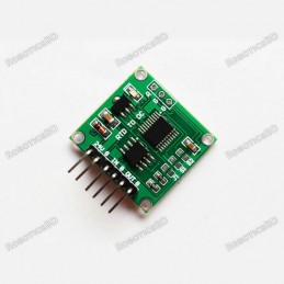
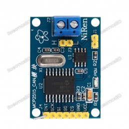
The TJA1050 CAN Bus Transceiver Module provides the interface between a CAN bus controller and the physical CAN bus differential lines.
CAN stands for Controller Area Network and it is often thought of as primarily an automotive communication bus since it is the standard for use with automobiles to connect all the electronics and sensors together and is brought out to the outside world via the ODB-II interface.
The CAN bus is in fact a good communication bus for many applications that use multiple distributed MCUs which need to interact with each other such as in factory automation or robotics.
The key features of the CAN bus is that it uses only 2 wires for bus communications and all MCUs connect to these same 2 wires.
This module is mainly handy for providing the interface for connecting a built-in CAN bus controller as found in some of the more advanced MCUs, to the physical differential bus lines that connect the different MCUs on the bus.
The physical bus consists of two end nodes which sit at the two ends of the bus. A cable of twisted pair wire which is usually shielded connect the two nodes. For bench-top type use, any 2 wires will work to connect the nodes. As the bus length increases or the environmental electrical noise increases, using twisted pair and adding shielding becomes more important.
The end nodes have a 120 ohm resistor that terminate the two ends of the bus. Each of these modules have a built-in 120 ohm resistor at location R3.
Other nodes can be added between the two end nodes. These can be spliced in-line or attached to the main bus using a short stub cable as long as the length is kept under 12″. These additional nodes do not use a 120 ohm termination resistor and so the resistor on the module should be removed from these additional nodes.
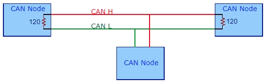
Typical CAN Bus Arrangement
These modules have zero ohm resistors in series with the CANH/CANL bus lines that can be optionally use to add series resistance. The module also has 2 small capacitors of approximately 30pF capacitance on these lines.
Since this module operates at 5V, if connecting to a 3.3V MCU a logic level translator will need to be used on the RX line going to the MCU. Using one on the TX line is optional.
The module has the Select pin of the TJA1050 tied to ground which puts the transceiver into the high-speed mode which is the normal mode of operation.
The main MCU CAN controller connection is via a 4-pin male header. The physical CAN bus is connected via a 2-pin male header. The headers are shipped separately so these connections can be wired instead of using headers if desired. The module will also fit the small 2.54mm screw terminals, but the terminal block will hang off the end of the board.
1 x 4 Header
1 x 2 Header
The module has 2 small M2 holes for mounting.
The CAN Bus is an underutilized bus and well worth exploring in the context of a distributed MCU system as it allows more of the system architecture to be moved to the software side of the equation which increases flexibility. You don’t see cars having to have their CAN bus rewired every time some module is changed to add or remove a feature. It is also very robust in order to survive the harsh automotive environment.
Operating Ratings | ||
Vcc | Range | 4.75 to 5.25V |
Temperature | Range | -40 to 150°C |
Icc | Typical recessive current | 5mA |
Typical dominant current | 50mA | |
Dimensions | L x W (PCB) | 22 x 11mm (0.87 x 0.43″) |
Country of Origin | China | |
Datasheets | NXP / Phlips | TJA1050 |
The latest price of TJA1050 CAN Bus Transceiver Module in Bangladesh is BDT 150 You can buy the TJA1050 CAN Bus Transceiver Module at best price from our RoboticsBD or visit RoboticsBD Office.
Please note that the product information provided on our website may not be entirely accurate as it is collected from various sources on the web. While we strive to provide the most up-to-date information possible, we cannot guarantee its accuracy. We recommend that you always read the product labels, warnings, and directions before using any product. |
Product Images are shown for illustrative purposes only and may differ from the actual product. |
Reference: RBD-0108
Works with standard (dual 5/3.3V) and 3.3V-only (for example, Pro Arduino) boards. Complies with USB Specification Revision 2.0 (Full-Speed 12Mbps Peripheral, Full-/Low-Speed 12Mbps/1.5Mbps Host) Supports HID devices, such as keyboards, mice, joysticks, etc. Compatible with Mass storage devices, such as USB sticks, memory card readers, external hard...
Reference: RBD-2212
Directly plug antenna interface. I2C bus communication. Multi-capacitor combined filter. Blue LED power indicator. High sensitivity(low noise RF input amplifier). High power auto gains control AGC circuit.
Reference: RBD-1331
High-quality BTA16-600B TRIAC AC Voltage: 220V/110V; 50/60Hz Rated current: 5A Logic: 3.3V/5V Peak Operating Current: 8A
Reference: RBD-0742
Input voltage(V): 6 – 27. Maximum current(A): 43. Input level(V): 3.3 – 5. Duty cycle: 0 – 100%. Path resistance: 16 mΩ at 25°C. Low quiescent current: 7 µA at 25°C.
Reference: RBD-0832
Power supply: 4.5V – 5.5V, 3.3V voltage regulator circuit board Positioning holes: 4 M2 screws positioning hole diameter of 2.2mm Control Interface: GND, VCC, MISO, MOSI, SCK, CS Size: 45 x 28mm Net weight: 6g
Reference: RBD-2921
Operating Voltage: 3.3V Resolution: 128 × 64 pixels Communication Interface: SPI (default) Display size: 55.01 × 27.49mm Driver: SSD1309Note: The component, colour & shape of the module may vary depending on our stock rotation.
Reference: RBD-0337
Brand: Waveshare
Detection depth: 48mm Power: 2.0V ~ 5.0V Dimension: 19.0mm * 63.0mm Mounting holes size: 2.0mm
Reference: RBD-1137
Fully Compatible with 10/100/1000Base-T Networks Integrated MAC and 10Base-T PHY Supports One 10Base-T Port with Automatic Polarity Detection and Correction Supports Full and Half-Duplex modes Programmable Automatic Retransmit on Collision Programmable Automatic Rejection of Erroneous Packets SPI Interface with Clock Speeds Up to 20 MHz For Arduino, SPI,...
Reference: RBD-2397
GPS Module NEO-6M Satellite Positioning Module for Arduino with MicroUSB
Reference: RBD-0313
Low power consumption, Low cost, and Compact size Read and write chip Fully integrated at 13.56MHz
Reference: RBD-2294
JQ6500 MP3 Voice sound module can play stereo MP3 files or standard mono audio files. The module has two different modes to operate in; serial communication mode (connecting to a microcontroller) or AD button control mode (module can be controlled with switches).
Reference: RBD-2470
3 Watt 8 Ohm Mini Speaker for Electronics Project with JST-PH2.0 Interface
Reference: RBD-2242
Wearable e-textile technology. Designed with large sew tabs LED Yellow Color
Reference: RBD-2659
Trigger Voltage: 5VDC Switching Voltage: 250VAC@30A; 30VDC@30A The module can be set high level or low-level trigger by the jumper Note: Relay brand may vary from actual product as our stock rotates.
Reference: RBD-2727
Module can be used to expand the digital I/O of an MCU using the I2C bus.
Reference: RBD-2475
5 counters with 2 end caps are bundled togeatherbezel size 1.85" x 0.94" (for 5 counters with 2 end caps) mounting hole size 1.72" x 0.875" (for 5 counters with 2 end caps) total depth (from front of button to the edge of the PCB) 1.6" single counter width 0.32"
Reference: RBD-2453
Fully self contained panel meter with dual red and blue display.
Reference: RBD-2928
Radio module (transmitter and receiver) operating in 433 MHz band with SPI communication interface. Powered by 2.7 V - 3.3 V, the outputs are goldpin connectors.It has an external antenna with SMA connector.
Reference: RBD-1328
Size: 0.96 inch Resolution: 128 x 64 Controlling Chip: SSH1106 Display Area: 21.74 x 10.86mm Driving Voltage: 3.3-5V Operating Temperature: -40~70 celsius Interface Type: IIC Light Color: White
Reference: RBD-0980
Dimensions : 66 x 66 x 3 mm. Weight : 25 gm. Supply Voltage : 5 VDC. Interface : IO . 8 x 8 = 64 RGB. Chip : WS2812.
Reference: RBD-1912
New L293D motor shield, the input voltage DC4.5-25V 600mA output current capability per channel 1.2A peak output current(non-repetitive) per channel Enable facility Overtemperature protection Logical “0” input voltage up to 1.5V(High noise immunity)
Reference: RBD-1773
Supply Voltage: 5V USB / 3.7V lithium battery Output Port: 3-wire audio interface/DIY pad Output Type: Analog signal Bluetooth name: VHM-314-V3.0 Bluetooth version: 5.0 Bluetooth passcode: no password Sound source: Bluetooth. USB-PC input(after the back pad is connected, the computer can be connected as a sound card though Micro) Operation method:...
Reference: RBD-0914
Driver Chip: MAX7219 Input Voltage: 3.7 to 5.3 V Input Current: 320 mA Display Dimensions: 32x32x6 (LxWxH) mm PCB Dimensions: 128×32 (LxW) mm
Reference: RBD-0413
SD card interface works with FAT16 or FAT32 formatted cards. 3.3v level shifter circuitry prevents damage to your SD card. Real-time clock (RTC) keeps the time going even when the Arduino is unplugged. The battery backup lasts for years. Included libraries and example code for both SD and RTC mean you can get going quickly Prototyping area for soldering...
Reference: RBD-2421
Product name: Humidifier Driver BoardColor: As showVoltage: DV 5VCurrent: 300mAPower: 2WFrequency: 110KHzSize: approx. 46 *20*17mm/1.81*0.79*0.67"
Reference: RBD-0575
Main color: Yellow Measure range: 0.00-14.00pH Resolution: 0.01pH Accuracy: ±0.05pH Calibration: two points automatic calibration
Reference: RBD-1834
PT100 to 0-5V Converter Voltage Signal Conditioner PCB-mounted
Reference: RBD-2042
Model: LilyPad Color: Purple Material: CCL Dimensions: 30 x 30 x 6 (LxWxH) mm. Weight: 3 gm.
Reference: RBD-0348
A Color-Coded Cable, with a standard male header connectors. Plug it straight into an Arduino or a Breadboard. No soldering is required. The Pulse Sensor has 3 holes around the outside edge which make it easy to sew it into almost anything. Visualization software (made in Processing) to instantly see the output of the sensor and for troubleshooting....
Reference: RBD-2488
Support Hardwired TCP/IP Protocols: TCP, UDP, ICMP, IPv4 ARP, IGMP, PPPoE, Ethernet 10BaseT/100BaseTX Ethernet PHY embedded Auto-Negotiation (Full-duplex and half duplex) Support Auto MDI/MDIX Simultaneously Supports to 4 independent sockets 0.18 µm CMOS technology 3.3V operation with 5V I/O signal tolerance Provide Serial Peripheral Interface (SPI MODE...
Reference: RBD-0397
Support CAN V2.0B technical standard, communication rate 1Mb / S. Module 5V DC power supply, SPI interface protocol control 0 to 8 bytes long data field. 8MHZ crystal oscillator 120Ω terminal resistance Use High-speed CAN transceiver TJA1050 Impedance matching, guaranteed drive capability, long-distance data transmission, prevent signal radiation The...
Reference: RBD-0350
100% Brand new and high quality STM32 Board Model: STM32F103C8T6. Core: ARM 32 Cortex-M3 CPU. Debug mode: SWD. 72MHz work frequency. 64K flash memory, 20K SRAM. RoboticsBD 2.0-3.6V power, I/O.